PSoC UDB 内 PLD/マクロセルによるアップダウン・カウンタ (6)
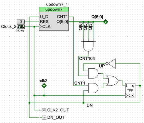
OPL3 の AM LFO を構成する要素のうち、周期 210 のアップダウン・カウンタ部を PSoC の UDB (Universal Digital Block) の PLD/マクロセル部で実現してみた回路を下に示します。
この回路全体で、UDB ひとつ (PLD 2 組、マクロセル 8 個) におさまっています。

「updown7」という名称になっているのが作成したコンポーネントで、7 ビット・アップダウン・カウンタの機能 (だけ) を持っています。 外部に設けた T-FF でアップ/ダウンの切り替えを行なっています。
動作としては、ダウンカウント (DN = 1, UP = 0) で「カウント 0」に達するとカウント方向をアップカウント (DN = 0, UP = 1) に切り替え、アップカウントで「カウント 105」に達するとカウント方向をダウンカウントに切り替えます。
実際には、カウント 0、カウント 105 を検出したのでは間に合わないので、ひとつ前のカウントである「カウント 1」および「カウント 104」を検出して T-FF を反転させています。 カウント 1 は updown7 モジュールの中で検出しています。
updown7 モジュールの Verilog コードを下に示します。
//`#start header` -- edit after this line, do not edit this line
// ========================================
//
// Copyright YOUR COMPANY, THE YEAR
// All Rights Reserved
// UNPUBLISHED, LICENSED SOFTWARE.
//
// CONFIDENTIAL AND PROPRIETARY INFORMATION
// WHICH IS THE PROPERTY OF your company.
//
// ========================================
`include "cypress.v"
//`#end` -- edit above this line, do not edit this line
// Generated on 10/21/2016 at 01:06
// Component: updown7
module updown7 (
	output  CNT1,
	output [6:0] Q,
	input   CLK,
	input   RES,
	input   U_D
);
	parameter width = 7;

//`#start body` -- edit after this line, do not edit this line

// count register
    reg [width-1:0] s;

// detect count 1 (and count 0) at down count
    assign CNT1 = (&(~s[width-1:1]) & U_D);

    assign Q = s;

    always @(posedge CLK or posedge RES) begin
      if (RES) // asynchronous reset
        s <= {width{1'b0}};
      else // count up/down
        s <= (s + { {width-1{U_D}}, 1'b1});
    end

//        Your code goes here

//`#end` -- edit above this line, do not edit this line
endmodule
//`#start footer` -- edit after this line, do not edit this line
//`#end` -- edit above this line, do not edit this line
cin も cout も使用しないので、Verilog の「+」演算子を使っています。
アップカウントはカウント・レジスタに 7'b000_0001 を加算することで実現し、一方、ダウンカウントはカウント・レジスタに 7'b111_1111 を加算することにより実現しています。
「カウント 1」は、カウント・レジスタの b6 から b1 までが全てゼロかどうかをデコードしています。 したがって、「カウント 1」と「カウント 0」がこの条件に当てはまりますが、ダウンカウント方向では先に「カウント 1」に到達するので問題なく、簡単化のためにデコードの条件から b0 を除外しています。
「カウント 104」は 104 = 7'h68 = 7'b110_1000 ですから、
(b6 & b5 & b3) = 1
をデコードすれは、アップカウント方向では「カウント 104」が最初に条件が成立するカウントになります。
「.rpt」ファイルの中から UDB / PLD / マクロセルの使用量に関するサマリの部分を下に示します。
----------------------------------------------------------
Technology mapping summary
----------------------------------------------------------

Resource Type               : Used : Free :  Max :  % Used
==========================================================

. . . . . <中略> . . . . .

UDB                         :      :      :      :
  Macrocells                :    8 :  184 :  192 :  4.17 %
  Unique P-terms            :   15 :  369 :  384 :  3.91 %
  Total P-terms             :   15 :      :      :


. . . . . <中略> . . . . .

----------------------------------------------------------
PLD Packing Summary
----------------------------------------------------------
            Resource Type : Used : Free :  Max :  % Used
    ====================================================
                     PLDs :    2 :   46 :   48 :   4.17%

        PLD Resource Type :     Average/LAB
    =======================================
                   Inputs :            6.00
                   Pterms :            7.50
               Macrocells :            4.00

. . . . . <中略> . . . . .

-----------------------------------------------------------
Final Placement Summary
-----------------------------------------------------------

     Resource Type :      Count : Avg Inputs : Avg Outputs
   ========================================================
               UDB :          1 :       8.00 :       8.00
8 個のマクロセルを使用し、PLD は 2 組使用して、UDB ひとつにおさまっています。
マクロセル部分のリスティングを下に示します。
----------------------------------------------------------
Macrocell listing
----------------------------------------------------------

MacroCell: Name=\updown7_1:MODULE_1:g1:a0:s_0\, Mode=(D-Register, Carry-Chain-Start)
   Total # of inputs        : 1
   Total # of product terms : 1
   List of special equations:
       Clock  = (clk2) => Global
       Cpt0 Equation   = (Q_0)
       Cpt1 Equation   = (0)
       Clock Enable: True
   Main Equation            : 1 pterm
   (
         Q_0
   );
   Cout = \updown7_1:MODULE_1:g1:a0:g0:u0:gof:g_arith(0):ga:cadd_0\
   Output = Q_0 (fanout=3)

MacroCell: Name=\updown7_1:MODULE_1:g1:a0:s_1\, Mode=(D-Register, Carry-Chain-Continue)
   Total # of inputs        : 2
   Total # of product terms : 2
   List of special equations:
       Clock  = (clk2) => Global
       Cpt0 Equation   = (DN * Q_1)
       Cpt1 Equation   = (!DN * !Q_1)
       Clock Enable: True
   Main Equation            : 2 pterms
   (
         !DN * !Q_1
       + DN * Q_1
   );
   Cin = \updown7_1:MODULE_1:g1:a0:g0:u0:gof:g_arith(0):ga:cadd_0\
   Cout = \updown7_1:MODULE_1:g1:a0:g0:u0:gof:g_arith(0):ga:cadd_1\
   Output = Q_1 (fanout=5)

. . . . . <中略> . . . . .

MacroCell: Name=\updown7_1:MODULE_1:g1:a0:s_6\, Mode=(D-Register, Carry-Chain-Last)
   Total # of inputs        : 2
   Total # of product terms : 2
   List of special equations:
       Clock  = (clk2) => Global
       Cpt0 Equation   = (DN * Q_6)
       Cpt1 Equation   = (!DN * !Q_6)
       Clock Enable: True
   Main Equation            : 2 pterms
   (
         !DN * !Q_6
       + DN * Q_6
   );
   Cin = \updown7_1:MODULE_1:g1:a0:g0:u0:gof:g_arith(0):ga:cadd_5\
   Cout = \updown7_1:MODULE_1:g1:a0:s_6_cout\
   Output = Q_6 (fanout=5)

MacroCell: Name=DN, Mode=(T-Register)
   Total # of inputs        : 7
   Total # of product terms : 2
   List of special equations:
       Clock  = (clk2) => Global
       Clock Enable: True
   Main Equation            : 2 pterms
   (
         !DN * Q_6 * Q_5 * Q_3
       + DN * !Q_6 * !Q_5 * !Q_4 * !Q_3 * !Q_2 * !Q_1
   );
   Output = DN (fanout=20)
Q_2 から Q_5 までは省略しましたが、最初の 7 個のマクロセルがアップダウン・カウンタ本体で、最後の 1 個の「Name=DN」となっているマクロセルが T-FF およびランダム・ロジック部分です。 「カウント 1」デコーダと「カウント 104」デコーダが PLD のプロダクト・ターム 2 個の中に収容されています。
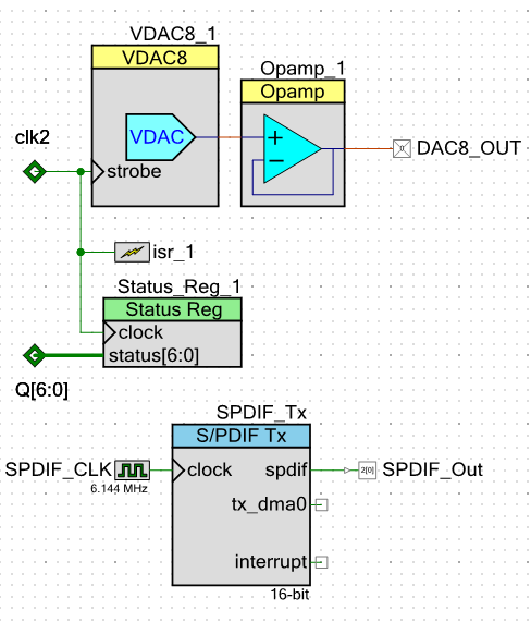
前述の回路に下の図のような回路を加えて、LFO 波形を SPDIF 経由でキャプチャしてみました。

アップダウン・カウンタ出力に接続したステータス・レジスタから値を読み出し、ビット・マスク、ビット・シフト、log - リニア変換、および SPDIF_Tx モジュール への出力などはソフトウェアで行いました。
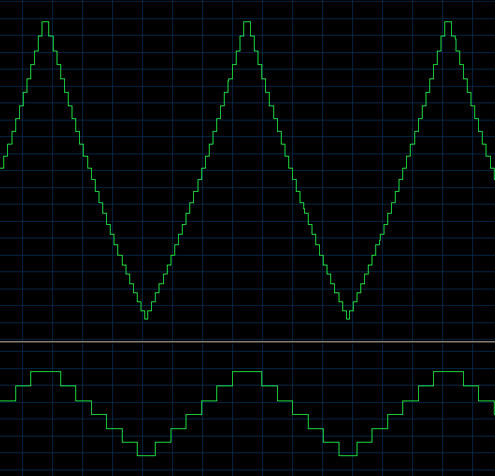
キャプチャ結果を波形編集ソフトで見たものを下に示します。

上のトレースが L ch におさめた DAM = 1 相当の波形、下のトレースが R ch におさめた DAM = 0 相当の波形で、実チップからキャプチャしたものと一致しています。